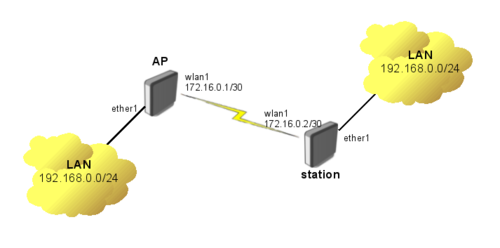
Uma topologia para quem necessita transportar trafego até um determinado ponto da rede, mas não gostaria de utilizar WDS, ou simplesmente tem um outro equipamento que está fechando o enlace, sendo ele Wireless, Elétrico ou Fibra Óptica.
Uma possibilidade que esse cenário possibilita é a possibilidade de usar mais de um VPLS para o mesmo destino podendo ser usando para redundância ou agregação do trafego.

Abaixo Veremos a configuração do AP (Acess Point)
/interface wireless
set wlan1 disabled=no ssid=MPLS frequency=5180 band=5ghz mode=bridge

# Configurando o IP
/ip address
add address=172.16.0.1/30 interface=wlan1

# habilitando o protocolo LDP
/mpls ldp
set enabled=yes lsr-id=172.16.0.1 transport-address=172.16.0.1
/mpls ldp interface
add interface=wlan1

#Configurando o Tunel VPLS
/interface vpls
add name=vpls1 remote-peer=172.16.0.2 vpls-id=1:1 disabled=no

# Adicionado o tunel VPLS e a porta de trafego que em nosso caso é a
# ether1
/interface bridge add name=bridge1
/interface bridge port
add bridge=bridge1 interface=ether1
add bridge=bridge1 interface=vpls1
Agora configuraremos o lado Station
# Configuração da interface wireless
/interface wireless
set wlan1 disabled=no ssid=MPLS band=5ghz mode=station

# Configurado o IP
/ip address
add address=172.16.0.2/30 interface=wlan1

# Habilitando o protocolo LDP nas interfaces
/mpls ldp
set enabled=yes lsr-id=172.16.0.2 transport-address=172.16.0.2
/mpls ldp interface
add interface=wlan1

#Adicionando o tunel VPLS
/interface vpls
add name=vpls1 remote-peer=172.16.0.1 vpls-id=1:1 disabled=no

# Adicionado o tunel VPLS e a porta de trafego que em nosso caso é a
# ether1
/interface bridge add name=bridge1
/interface bridge port
add bridge=bridge1 interface=ether1
add bridge=bridge1 interface=vpls1
Antes de executar o próximo comando verifique se o link Wireless está estabelecido.
Após a confirmação é possível verificar o Status do LDP
[admin@MikroTik] /mpls ldp neighbor> print
Flags: X - disabled, D - dynamic, O - operational, T - sending-targeted-hello, V - vpls
 #      TRANSPORT    LOCAL-TRANSPORT PEER           SEND-TARGETED ADDRESSES
 0 DOTV 172.16.0.2   172.16.0.1      172.16.0.2:0   no            172.16.0.2

[admin@MikroTik] /mpls ldp neighbor> .. .. forwarding-table print
Flags: L - ldp, V - vpls, T - traffic-eng
 #   IN-LABEL        OUT-LABELS      DESTINATION    INTERFACE    NEXTHOP
 0   expl-null
 1 V 18                              vpls1
Aqui podemos verificar se o VPLS está conectado
[admin@MikroTik] /interface vpls> monitor vpls1 once
       remote-label: 17
        local-label: 18
      remote-status:
  transport-nexthop: 172.16.0.2
     imposed-labels: 17
Caso necessite fazer um ponto-multi-ponto é necessário alterar o modo da AP de bridge para AP-Bridge e adicionar no novo tunel VPLS como segue abaixo.
# Alterando do bridge para AP-Bridge
/interface wireless
set wlan1 mode=ap-bridge

# Configurando o novo Tunel VPLS
/interface vpls
add name=vpls2 remote-peer=172.16.0.3 vpls-id=2:2 disabled=no

# Adicionando o tunel na bridge
/interface bridge port
add bridge=bridge1 interface=vpls2
Aqui é como deve ficar a nova station que participará do novo tunel.
# Configurando a interface wirelss
/interface wireless
set wlan1 disabled=no ssid=MPLS band=5ghz mode=station

# Configurando o IP
/ip address
add address=172.16.0.3/30 interface=wlan1

# Habilitando o LDP
/mpls ldp
set enabled=yes lsr-id=172.16.0.3 transport-address=172.16.0.3
/mpls ldp interface
add interface=wlan1

# Adicionando o Tunel VPLS
/interface vpls
add name=vpls1 remote-peer=172.16.0.1 vpls-id=2:2 disabled=no

# Adicionando as portas na bridge
/interface bridge add name=bridge1
/interface bridge port
add bridge=bridge1 interface=ether1
add bridge=bridge1 interface=vpls1
Quando utilizamos MPLS o tamanho adicionamos os labels aos IP frames isso altera o tamanho de MTU minimo, nesse caso é necessário alterar a MTU das interfaces para não gerarmos pacotes fragmentados nessa rede. Faremos isso com o comando abaixo.
/mpls interface set 0 mpls-mtu=1522


